Way back in February 2025, I was sent a pair of Reyax LoRa modules to try out and review.They duly went into the increasingly dangerous pile of interesting hardware waiting for attention and frankly, I never got around to using them.Havin no idea how to use LoRa and moving home didn’t help – a multi-month process.
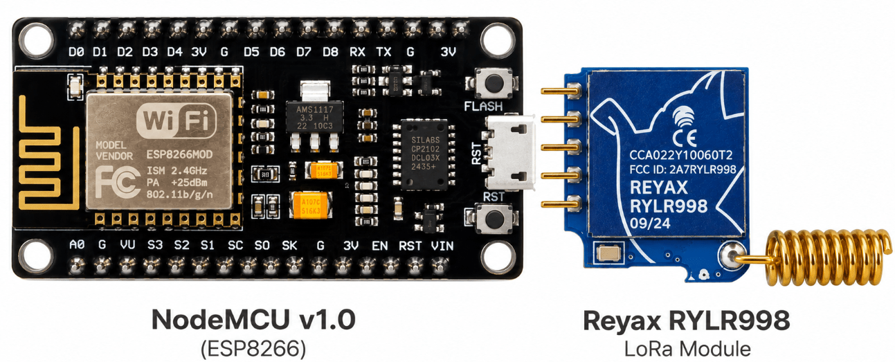
That is until today: I decided to start with absolutely no grand plan — just two NodeMCU ESP8266 boards (just because I have them), two identical Reyax RYLR998 LoRa modules and the desire to see how difficult it would be to get a simple long-range wireless link working.Trust me, I’ve tried ALL ways to get a signal down to my letterbox – including 433Mhz dedicated sensor and receiver boxes from AliExpress (one way) – let me first bore you… my office is surrounded by thick stone inside a cavehome – behind my room a mountain (large hill) – in front, the living room – all walls are SOLID – out of the 3-layer breezeblock exit to a semi-enclosed foyer – again breezeblock – around the BBQ area – stone and breezeblock again stopping line of sight… across our car park area, large enough for 3 cars, to our gates – total up to now 70 steps – I’m tall.Then down a 20 degree curved slope – our shared footpath with our neighbour – 76 more steps to our letterbox – a grand total of 146 steps.
First things first – talking to the modules The RYLR998 modules are wonderfully straight-forward once you know what they expect.Connected to a USB serial adapter, both respond (at default 115Kbaud) to a simple: AT with: +OK They also happily reveal their firmware version: +VER=RYLR998_REYAX_V1.2.3 That was encouraging.Both modules were alive.
I configured them with different addresses (1 and 2 – the default was 0) but with the same network ID and radio frequency, then I tried sending messages between them and rather pleasingly: It worked.Adding the NodeMCUs Next came a pair of very ordinary NodeMCU ESP8266 boards.No Bluetooth, fancy displays or anything complicated — just a couple of ESP8266s talking to the LoRa modules over software serial at 115K Baud.
The LoRa module’s TX and RX pins were connected to the ESP8266 using D6 and D7, with the usual crossed-over serial arrangement.The first experiment couldn’t have been much simpler: send an ON command to one NodeMCU from the other – and turn its built-in blue LED on.Send OFF and turn it off.
Soon I was doing this from one side of the property to the other.Rock walls are surprisingly effective My house isn’t exactly ideal for radio experiments.I took the “remote” NodeMCU +LoRa board, now running on a USB battery… firstly to our gate and then down to the letterbox.
At the final destination, rotating the LoRa transceiver by only a small amount could make the difference between success and failure but – that’s better than I’d managed up until today.That immediately made the next idea obvious: why not put the home transmitter end on Wi-Fi? LoRa meets ESPHome The indoor NodeMCU was moved from the Arduino IDE to ESPHome.It now connects to any of several available Wi-Fi networks and provides a simple web interface as well as connecting directly into Home Assistant.
The first control was deliberately basic: a single switch in the Web UI.Turn it on: Wi-Fi ↓ ESP8266 ↓ LoRa ON command ↓ Remote Node ↓ LED ON Turn it off and the remote LED turns off.That meant I could move the LoRa transmitter around the house, power it from a USB battery and control the remote node directly from my phone.
But did the remote node actually receive the command? Sending a LoRa command is one thing.Knowing that it actually arrived is rather more useful… so the remote NodeMCU (Arduino code) was modified to send a message back after completing each command.DONE:ON or: DONE:OFF The indoor ESPHome node listens continuously for those replies and displays the result in both its web interface and in Home Assistant.
The result is a proper two-way LoRa link: ESPHome ↓ LoRa command ↓ Remote Node ↓ Action completed ↓ LoRa acknowledgement ↓ ESPHome Signal strength for free The returned LoRa messages also contain useful radio information.The transmitter can therefore extract the received signal strength and signal-to-noise information from the returning packet and display: signal strength; SNR; a simple quality rating from Excellent through to Rubbish.That immediately made this little project a rather useful LoRa test rig as well as a remote control system.
Adding a remote input The next experiment was even more interesting: GPIO14 on the remote NodeMCU was configured as an input with its internal pull-up enabled.A simple connection between the GPIO pin and ground changes its state.When that happens, the remote node sends: INPUT:ON or: INPUT:OFF back over LoRa.
The ESPHome transceiver turns those messages into a proper binary sensor, visible both in its own web interface and in Home Assistant.So we now have: Remote sensor ↓ ESP8266 GPIO ↓ LoRa ↓ ESP8266 + ESPHome ↓ Wi-Fi Home Assistant And that gave me an idea… The letterbox at the bottom of the hill is metal, so my original thoughts about various types of presence sensing were becoming unnecessarily complicated and battery-consuming.Then I realised something rather obvious… the postman can only operate one part of the letterbox: the flap.
A tiny microswitch attached to that flap could trigger the GPIO input on the remote unit.That state can then be sent straight back to Home Assistant.A simple, long-range, battery-powered “you’ve got post” sensor.
And that’s probably where this experiment is heading next.Not bad for an afternoon’s work Starting with two LoRa modules which had been sitting unused for 18 months, I now have: two-way LoRa communications; remote LED control; command acknowledgements; signal-strength monitoring; a remote GPIO sensor; a Wi-Fi-connected ESPHome gateway; Home Assistant integration.MY THANKS to Rayax for getting me into this in the first place.
And the whole thing is (not necessarily) built from two extremely cheap and familiar ESP8266 NodeMCU boards and the two Rayax modules.As I’m only using 4 signal wires (RX, TX, LED, INPUT – and LED is built-in so no wire necessary or shown here) any old ESP12 module would do.Not bad for a first proper afternoon playing with LoRa – indeed the first time I’ve touched LoRa other than looking at the boards (gnd, tx, rx and 3v3 – I didn’t touch the RST pin).
Don’t even ask why I didn’t use the second G pin (NodeMCU) for the button return – ChatGPT is brilliant at cat photos but rubbish at wiring – I’m going back to PowerPoint.Now I just need to sort out the wiring so it doesn’t fall apart every time I breathe near it… I can develop this into a full source code blog if there’s enough interest..or I might do it regardless…
Read More